Complete Robotics Design & Implementation
Left-Hand Rule Algorithm • PID Wall Following • Encoder Fusion Control


An autonomous maze-solving robot built from scratch using an ATmega328P microcontroller (Arduino Nano). This MicroMouse navigates through unknown mazes using the left-hand rule algorithm, combining ultrasonic sensor feedback with motor encoder data for precise movement control.
The robot features a dual feedback control system that fuses:
- PID-based wall following using 3 HC-SR04 ultrasonic sensors
- Encoder-based dead reckoning for accurate turns and straight-line tracking
Goal: Design and build a fully autonomous robot capable of navigating and solving standard maze configurations without human intervention.

🎬 Final assembled MicroMouse robot ready for maze navigation
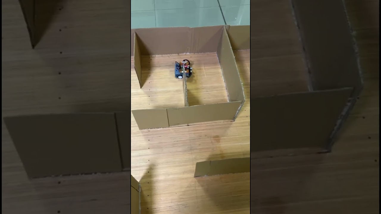
Click the image above or watch the MicroMouse autonomously navigate through a maze using the left-hand rule algorithm
Follow these steps to build and run your own MicroMouse:
flowchart LR
    A[1️⃣ Clone Repo] --> B[2️⃣ Assemble Hardware]
    B --> C[3️⃣ Print Chassis]
    C --> D[4️⃣ Wire Components]
    D --> E[5️⃣ Flash Code]
    E --> F[6️⃣ Calibrate]
    F --> G[🎉 Run!]
git clone https://github.com/Ravinx001/MicroMouse.git
cd MicroMouseEnsure you have all components from the Bill of Materials:
- Arduino Nano (ATmega328P)
- TB6612FNG motor driver
- 2× N20 gear motors with encoders
- 3× HC-SR04 ultrasonic sensors
- 7.4V LiPo battery
- Wheels and caster
- Download
body_3D_design/micromouse_body_3d_design.stl - Print with PLA/PETG, 0.2mm layer height, 25% infill
- Allow 4+ hours for printing
Connect components according to the Pin Configuration table:
| Connection | Arduino Pin |
|---|---|
| Left Motor PWM | D5 |
| Right Motor PWM | D3 |
| Motor Driver STBY | D8 |
| Left Ultrasonic TRIG/ECHO | A4/A5 |
| Front Ultrasonic TRIG/ECHO | D9/D10 |
| Right Ultrasonic TRIG/ECHO | D11/D12 |
| Left Encoder A/B | A0/A1 |
| Right Encoder A/B | A2/A3 |
Windows:
# Install WinAVR or AVR Toolchain
# Download from: https://www.microchip.com/mplab/avr-support/avr-and-arm-toolchains-c-compilers

# Update COM port in Makefile
notepad Makefile  # Change PORT = COM3 to your port

# Build and flash
make build
make flash
Linux/macOS:
# Install AVR toolchain
sudo apt install gcc-avr avr-libc avrdude  # Debian/Ubuntu
brew install avr-gcc avrdude               # macOS

# Update port and flash
# Linux: PORT = /dev/ttyUSB0
# macOS: PORT = /dev/cu.usbserial-*
make build
make flash# Flash calibration program
make calibrate
# Open Serial Monitor at 9600 baud
# Manually rotate each wheel one full revolution
# Note the tick count displayed
# Update TICKS_PER_REVOLUTION in include/config.h- Place robot at maze entrance
- Power on - wait for 3-second countdown
- Watch it solve the maze autonomously!
| Check | Action |
|---|---|
| ☐ Motors spin correctly | Both wheels forward when expected |
| ☐ Sensors read distances | Open Serial Monitor, verify L/F/R readings |
| ☐ 90° turns are accurate | Adjust TURN_90_COMPENSATION if needed |
| ☐ Wall following is smooth | Tune PID gains if oscillating |
💡 Tip: Start with the robot in a simple straight corridor before testing in a full maze!
Implements the classic wall-following algorithm with priority-based decision making:
- Priority 1: Turn LEFT if left wall is absent
- Priority 2: Go FORWARD if path is clear
- Priority 3: Turn RIGHT if right wall is absent
- Priority 4: Turn AROUND (180°) at dead ends
Advanced sensor fusion combining two independent control mechanisms:
- Encoder Feedback (40%): Quadrature encoders for precise positioning
- Wall PID Control (60%): Real-time distance regulation from walls
Three HC-SR04 sensors provide 180° environmental awareness:
- Left, Front, and Right wall detection
- Range: 2cm to 400cm with ±3mm accuracy
- 100ms update rate with exponential smoothing filter
TB6612FNG dual H-bridge driver with PWM speed control:
- Independent speed control for differential steering
- Active braking capability for precise stops
- Hardware timer-based PWM generation
| Component | Part Number | Function |
|---|---|---|
| Microcontroller | ATmega328P (Arduino Nano) | Main processing unit @ 16MHz |
| Motor Driver | TB6612FNG | Dual H-bridge motor control |
| Motors | N20 DC Gear Motors (x2) | Differential drive propulsion |
| Ultrasonic Sensors | HC-SR04 (x3) | Wall distance measurement |
| Encoders | Quadrature Encoders (x2) | Wheel position feedback |
| Power | 7.4V LiPo Battery | Portable power source |
| Voltage Regulator | AMS1117-5V | 5V logic level regulation |
flowchart TB
    subgraph POWER["⚡ Power Supply"]
        BAT[🔋 7.4V LiPo Battery]
        REG[AMS1117 5V Regulator]
        BAT --> REG
    end

    subgraph SENSING["📡 Sensor Array"]
        LEFT[HC-SR04 Left]
        FRONT[HC-SR04 Front]
        RIGHT[HC-SR04 Right]
        ENCL[Left Encoder]
        ENCR[Right Encoder]
    end

    subgraph PROCESSING["🧠 Processing Unit"]
        MCU[ATmega328P<br/>16MHz]
        PID[PID Controller]
        MAZE[Maze Solver<br/>Left-Hand Rule]
        FUSION[Sensor Fusion<br/>40% Enc + 60% Wall]
    end

    subgraph ACTUATION["⚙️ Motor Control"]
        DRIVER[TB6612FNG<br/>Motor Driver]
        MOTORL[Left Motor]
        MOTORR[Right Motor]
    end

    REG -->|5V| MCU
    LEFT --> MCU
    FRONT --> MCU
    RIGHT --> MCU
    ENCL --> MCU
    ENCR --> MCU

    MCU --> PID
    MCU --> MAZE
    PID --> FUSION
    FUSION --> DRIVER
    MAZE --> DRIVER

    DRIVER --> MOTORL
    DRIVER --> MOTORR

    BAT -->|7.4V Direct| DRIVER
flowchart TD
    START([🚀 System Start]) --> INIT[Initialize Peripherals<br/>UART, Timers, GPIO, PWM]
    INIT --> SENSORS[Initialize Sensors<br/>& Encoders]
    SENSORS --> DELAY[3 Second Countdown]
    DELAY --> LOOP{Main Control Loop}

    LOOP --> READ_SENS[Read Ultrasonic<br/>Sensors @ 100ms]
    READ_SENS --> READ_ENC[Read Encoder<br/>Counts]
    READ_ENC --> WALL_STATE{Determine<br/>Wall State}

    WALL_STATE -->|Both Walls| CENTER[Center Between<br/>Walls PID]
    WALL_STATE -->|Left Only| FOLLOW_L[Follow Left<br/>Wall PID]
    WALL_STATE -->|Right Only| FOLLOW_R[Follow Right<br/>Wall PID]
    WALL_STATE -->|No Walls| STRAIGHT[Encoder-Only<br/>Straight Drive]
    WALL_STATE -->|Front Wall| DECISION[Maze Decision<br/>Required]

    CENTER --> FUSION[Sensor Fusion<br/>Enc 40% + Wall 60%]
    FOLLOW_L --> FUSION
    FOLLOW_R --> FUSION
    STRAIGHT --> ENC_ONLY[Encoder<br/>Correction Only]

    FUSION --> MOTORS[Apply Motor<br/>Speeds]
    ENC_ONLY --> MOTORS

    DECISION --> CHECK{Check<br/>Openings}
    CHECK -->|Left Open| TURN_L[Turn Left 90°]
    CHECK -->|Front Clear| FWD[Continue Forward]
    CHECK -->|Right Open| TURN_R[Turn Right 90°]
    CHECK -->|Dead End| TURN_180[Turn Around 180°]

    TURN_L --> MOTORS
    FWD --> MOTORS
    TURN_R --> MOTORS
    TURN_180 --> MOTORS

    MOTORS --> LOOP
stateDiagram-v2
    [*] --> FORWARD: Start

    FORWARD --> LEFT_OPEN: Left sensor > threshold
    FORWARD --> FRONT_BLOCKED: Front sensor < threshold
    FORWARD --> FORWARD: Continue straight

    LEFT_OPEN --> WAIT_DELAY: Debounce 500ms
    WAIT_DELAY --> TURN_LEFT: Opening confirmed
    WAIT_DELAY --> FORWARD: False positive

    TURN_LEFT --> FORWARD: Turn complete

    FRONT_BLOCKED --> CHECK_LEFT: Stop & sense
    CHECK_LEFT --> TURN_LEFT: Left open
    CHECK_LEFT --> CHECK_RIGHT: Left blocked
    CHECK_RIGHT --> TURN_RIGHT: Right open
    CHECK_RIGHT --> TURN_180: Dead end

    TURN_RIGHT --> FORWARD: Turn complete
    TURN_180 --> FORWARD: Turn complete

    note right of WAIT_DELAY
        MAZE_OPENING_DELAY
        prevents false triggers
    end note
| Arduino Pin | ATmega328P | TB6612FNG | Function |
|---|---|---|---|
| D7 | PD7 | AIN1 | Left Motor Direction 1 |
| D6 | PD6 | AIN2 | Left Motor Direction 2 |
| D5 | PD5 (OC0B) | PWMA | Left Motor PWM Speed |
| D4 | PD4 | BIN1 | Right Motor Direction 1 |
| D2 | PD2 | BIN2 | Right Motor Direction 2 |
| D3 | PD3 (OC2B) | PWMB | Right Motor PWM Speed |
| D8 | PB0 | STBY | Standby (Active HIGH) |
| Sensor | TRIG Pin | ECHO Pin |
|---|---|---|
| Left | A4 (PC4) | A5 (PC5) |
| Front | D9 (PB1) | D10 (PB2) |
| Right | D11 (PB3) | D12 (PB4) |
| Encoder | Phase A | Phase B |
|---|---|---|
| Left Motor | A0 (PC0) | A1 (PC1) |
| Right Motor | A2 (PC2) | A3 (PC3) |
A custom chassis was designed in Autodesk Fusion 360 to house all components securely.

Custom 3D-printed chassis design in Fusion 360
- ✅ Integrated motor mounts with vibration dampening
- ✅ Precise sensor mounting angles for optimal detection
- ✅ Battery compartment with secure fit
- ✅ Easy access for programming and debugging
- ✅ Ventilation slots for electronics cooling
| Parameter | Value |
|---|---|
| Material | PLA or PETG |
| Layer Height | 0.2mm |
| Infill | 25% |
| Supports | Yes (for motor mounts) |
| Print Time | ~4 hours |
- AVR-GCC Toolchain (avr-gcc, avr-objcopy, avrdude)
- Arduino Nano or compatible ATmega328P board
- USB-to-Serial driver (CH340 for clone Nanos)
# Clone the repository
git clone https://github.com/Ravinx001/MicroMouse.git
cd MicroMouse

# Build the project
make build

# Check memory usage (critical - RAM near capacity!)
make size

# Flash to Arduino Nano (update COM port in Makefile first)
make flash

# Clean build artifacts
make clean

# Run encoder calibration tool
make calibrateBefore flashing, update the PORT variable in Makefile:
# Windows: COM3, COM4, etc.
# Linux: /dev/ttyUSB0, /dev/ttyACM0
# Mac: /dev/cu.usbserial-*
PORT = COM3| Memory | Used | Available | Usage |
|---|---|---|---|
| Flash | ~12KB | 32KB | ~37% |
| RAM | ~1.8KB | 2KB | ~90% |
⚠️ Warning: RAM usage is near capacity. Avoid adding large buffers or arrays.
All tunable parameters are centralized in include/config.h.
// Motor Speeds
#define MOTOR_SPEED 110      // Base forward speed (0-255)
#define TURN_SPEED 80        // Turning speed (0-255)

// PID Gains
#define PID_KP 1.2f          // Proportional gain
#define PID_KI 0.03f         // Integral gain
#define PID_KD 0.6f          // Derivative gain

// Wall Following
#define TARGET_WALL_DISTANCE 8    // Target distance from walls (cm)
#define FRONT_STOP_DISTANCE 15    // Stop when front wall closer (cm)

// Maze Detection
#define MAZE_LEFT_THRESHOLD 20    // Opening detection threshold (cm)
#define MAZE_OPENING_DELAY 500    // Debounce delay (ms)

// Control Fusion Weights
#define ENCODER_WEIGHT 0.4f       // Encoder contribution
#define WALL_WEIGHT 0.6f // Wall PID contribution| Problem | Solution |
|---|---|
| Robot oscillates/wobbles | Reduce PID_KP or increase PID_KD |
| Drifts on straight paths | Increase ENCODER_CORRECTION_GAIN |
| Turns overshoot | Increase TURN_90_COMPENSATION |
| Turns undershoot | Decrease TURN_90_COMPENSATION |
| False turn triggers | Increase MAZE_OPENING_DELAY |
| Too slow reaction | Decrease CONTROL_PERIOD_MS |
📚 Detailed tuning guide: See CONFIG_PARAMETERS_GUIDE.md
| Specification | Value | Notes |
|---|---|---|
| Microcontroller | ATmega328P | 16MHz, 32KB Flash, 2KB RAM |
| Operating Voltage | 5V Logic | 7.4V battery input |
| Motor Voltage | 6-7.4V | Direct from battery |
| Sensor Range | 2-400cm | HC-SR04 ultrasonic |
| Encoder Resolution | 356 ticks/rev | Quadrature decoding |
| Control Loop Rate | 20Hz | 50ms period |
| Sensor Update Rate | 10Hz | 100ms period |
| Turn Accuracy | ±5° | Encoder-controlled |
| Max Speed | ~30cm/s | At MOTOR_SPEED=110 |
| Dimensions | ~12×10×8cm | LxWxH approximate |
| Weight | ~200g | Including battery |
MicroMouse/
├── 📄 README.md                          # This file
├── 📄 LICENSE                            # MIT License
├── 📄 Makefile                           # Build system
├── 📄 CONFIG_PARAMETERS_GUIDE.md         # Detailed tuning guide
├── 📄 TURN_CONFIG_SIMPLIFIED.md          # Turn calibration guide
│
├── 📂 src/                               # Source files
│   ├── main.c                            # Main control loop & maze logic
│   ├── motors.c                          # TB6612FNG motor driver
│   ├── sensors.c                         # HC-SR04 ultrasonic sensors
│   ├── uart.c                            # Serial communication
│   └── utils.c                           # Timing utilities (millis, micros)
│
├── 📂 include/                           # Header files
│   ├── config.h                          # ⚙️ ALL tunable parameters
│   ├── motors.h                          # Motor driver interface
│   ├── sensors.h                         # Sensor interface
│   ├── uart.h                            # UART interface
│   └── utils.h                           # Utility functions
│
├── 📂 samples/                           # Example implementations
│   ├── 90_turning_and_wall_following/    # Turn + wall follow demo
│   └── optimized_wall_following_with_ultrasonic/  # PID tuning demo
│
├── 📂 arduino_codes/                     # Arduino IDE versions
│   └── wall_following_tune.ino           # Wall following tuning sketch
│
├── 📂 body_3D_design/                    # Chassis design files
│   ├── micromouse_body_3d_design.f3d     # Fusion 360 source
│   ├── micromouse_body_3d_design.stl     # 3D printable STL
│   └── micromouse_body_3d_design.PNG     # Design preview
│
├── 📂 photos/                            # Build documentation
│   └── final_view_of_micro_mouse.jpeg    # Finished robot photo
│
├── 📂 video/                             # Demo videos
│   └── Micro Mouse Full Video.mp4        # Full operation demo
│
├── 📂 build/                             # Compiled output (generated)
│
└── 📂 .github/                           # GitHub configuration
    └── copilot-instructions.md           # AI coding assistant guide
flowchart LR
    subgraph INPUT
        SP[Setpoint<br/>8cm target]
        PV[Process Variable<br/>Actual distance]
    end

    subgraph PID["PID Controller"]
        E[Error<br/>SP - PV]
        P[P Term<br/>Kp × error]
        I[I Term<br/>Ki × ∫error]
        D[D Term<br/>Kd × d/dt error]
        SUM((Σ))
    end

    subgraph OUTPUT
        CORR[Correction<br/>-40 to +40]
        ML[Left Motor<br/>Speed ± correction]
        MR[Right Motor<br/>Speed ∓ correction]
    end

    SP --> E
    PV --> E
    E --> P
    E --> I
    E --> D
    P --> SUM
    I --> SUM
    D --> SUM
    SUM --> CORR
    CORR --> ML
    CORR --> MR
flowchart TD
    subgraph ENCODERS["Encoder Feedback"]
        EL[Left Encoder<br/>Ticks]
        ER[Right Encoder<br/>Ticks]
        DIFF[Tick Difference<br/>L - R]
        ENC_CORR[Encoder Correction<br/>diff × gain]
    end

    subgraph WALLS["Wall PID Feedback"]
        SENS[Ultrasonic<br/>Sensors]
        FILTER[Low-Pass<br/>Filter α=0.6]
        PID_CALC[PID<br/>Calculation]
        WALL_CORR[Wall Correction]
    end

    subgraph FUSION["Sensor Fusion"]
        WEIGHT[Weighted Sum<br/>40% Enc + 60% Wall]
        TOTAL[Total Correction]
    end

    EL --> DIFF
    ER --> DIFF
    DIFF --> ENC_CORR

    SENS --> FILTER
    FILTER --> PID_CALC
    PID_CALC --> WALL_CORR

    ENC_CORR -->|× 0.4| WEIGHT
    WALL_CORR -->|× 0.6| WEIGHT
    WEIGHT --> TOTAL

    TOTAL --> MOTORS[Motor Speeds]
| Problem | Possible Cause | Solution |
|---|---|---|
| Robot doesn't move | STBY pin LOW | Check D8 is HIGH after motors_enable() |
| Erratic sensor readings | Electrical noise | Add 0.1µF caps near sensor VCC pins |
| Turns are inaccurate | Wrong encoder count | Run make calibrate and update TICKS_PER_REVOLUTION |
| Robot drifts left/right | Encoder polarity | Check encoder wiring or swap A/B phases |
| Oscillates in corridor | PID gains too high | Reduce PID_KP or increase PID_KD |
| Misses wall openings | Threshold too low | Increase MAZE_LEFT_THRESHOLD |
| False opening detection | Delay too short | Increase MAZE_OPENING_DELAY |
| Won't compile | Missing toolchain | Install avr-gcc and avr-libc |
| Flash fails | Wrong COM port | Update PORT in Makefile |
| RAM overflow | Too many variables | Remove debug strings, optimize buffers |
Connect at 9600 baud to view real-time status:
ENC L:1234 R:1230 D:4 | BOTH L:7cm R:8cm
ENC L:1280 R:1278 D:2 | LEFT L:6cm
>>> TURNING LEFT 90° <<<
Turn complete! Ticks: 287 (Target: 282)
| Qty | Component | Specification | Notes |
|---|---|---|---|
| 1 | Arduino Nano | ATmega328P, CH340 | Or compatible clone |
| 1 | TB6612FNG Module | Dual H-Bridge | Handles 1.2A/channel |
| 2 | N20 Gear Motors | 6V, 100-300 RPM | With encoder mount |
| 2 | Quadrature Encoders | ~360 PPR | Magnetic or optical |
| 3 | HC-SR04 | Ultrasonic sensor | 2-400cm range |
| 1 | 7.4V LiPo Battery | 300-500mAh | 2S configuration |
| 1 | AMS1117-5V | Voltage regulator | Or LM7805 |
| 2 | Wheels | 42mm diameter | Fits N20 shaft |
| 1 | Caster Wheel | Ball or swivel | Rear support |
| - | Jumper Wires | Various | For connections |
| - | 3D Printed Chassis | PLA/PETG | See design files |
This project demonstrates proficiency in:
- ✅ Embedded C Programming - Direct register manipulation, ISRs, hardware timers
- ✅ Control Systems - PID implementation, sensor fusion, state machines
- ✅ Algorithm Design - Left-hand rule maze solving, decision trees
- ✅ Electronics Integration - Motor drivers, sensor interfaces, power management
- ✅ 3D CAD Design - Fusion 360 parametric modeling
- ✅ Build Systems - Makefile-based compilation and flashing
- ✅ Technical Documentation - Comprehensive project documentation
Contributions are welcome! Areas for improvement:
- Flood-fill algorithm implementation
- Speed run optimization after maze learning
- IR sensor alternative to ultrasonic
- Bluetooth/WiFi telemetry
- PCB design for cleaner integration
- OLED display for status
- Fork the repository
- Create a feature branch (
git checkout -b feature/FloodFill) - Commit changes (
git commit -m 'Add flood-fill algorithm') - Push to branch (
git push origin feature/FloodFill) - Open a Pull Request
This project is licensed under the MIT License - see the LICENSE file for details.
Project Maintainer
📧 Email: rav.business.lak@gmail.com
🐙 GitHub: @Ravinx001
💼 LinkedIn: Ravindu Amarasekara
Community
💬 Discussions: Use GitHub Discussions for questions
🐛 Issues: Report bugs via GitHub Issues